


As we mentioned earlier, the original oven circuitry has the two upper elements connected parallel with the two lower elements. After doing some rewiring, by disconnecting all the controllers from the circuit and adding the micro-controller in, we got a circuit that look as following:
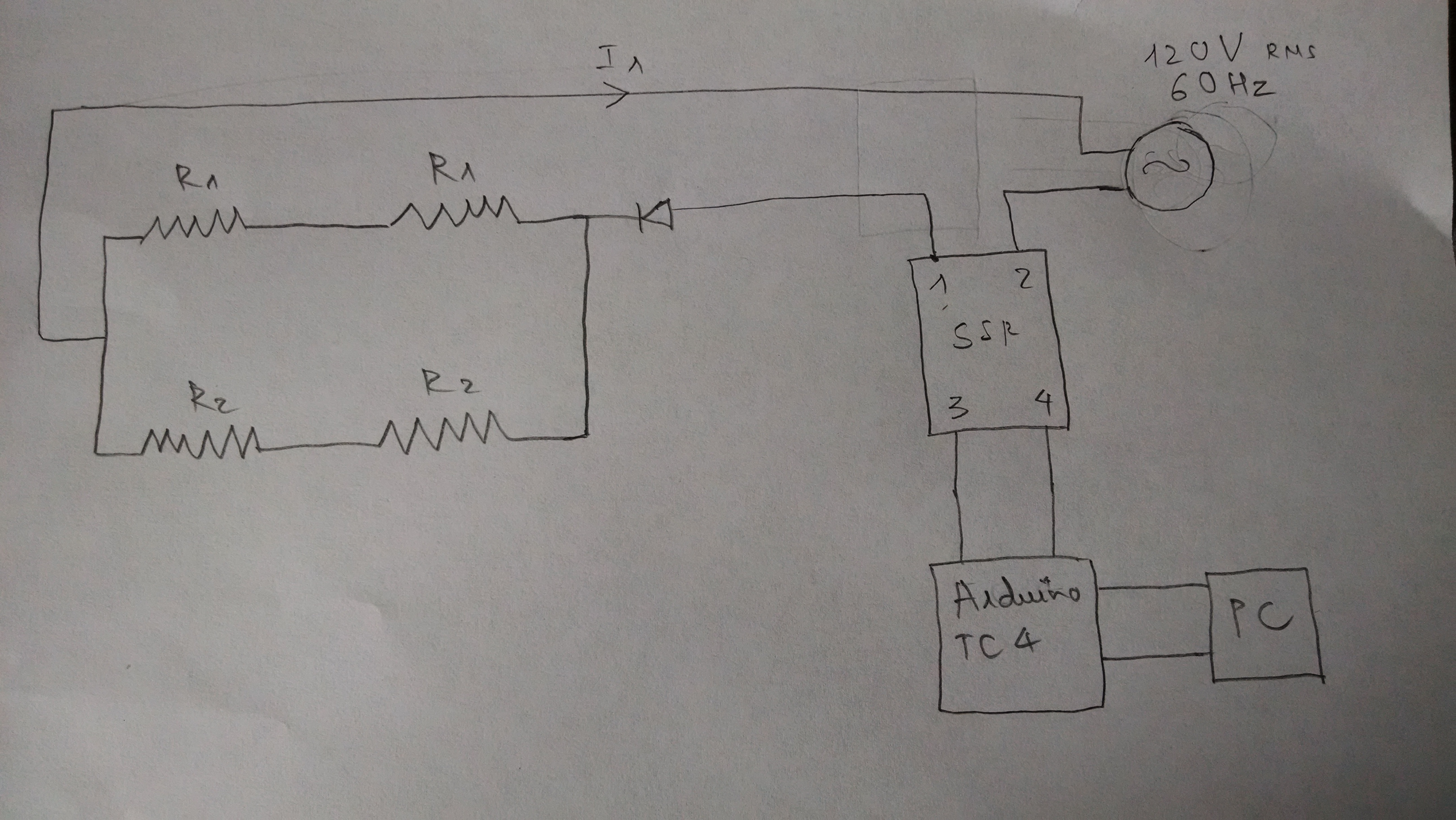
Circuit 1: Upper // Lower
There are many different ways that we can connect these heating elements together and therefore we figure that before we do any more rewiring, we should do some analysis on how different circuits will result in different behaviors and efficiency. Hence, first we’ll analyze this circuit 1.
As we can notice, the signal coming from the solid state relay before getting to the heating elements has to pass through the diode, which function is to allow an electric current to pass in one direction while blocking current in the opposite direction. In other words, the diode basically converts the AC signal coming from the SSR into DC signal. In this case, it only allows the positive part of the signal to go through and blocks all the negative counterpart. A simple diagram of the functionality of the diode is shown below:

Diode Functionality
We know that the power supply from the wall is of type 120V rms and 60Hz. It’s an AC power signal which is converted into a DC signal after passing through the diode. This kind of circuit is call a rectifier.
http://www.electronics-tutorials.ws/diode/diode_5.html
A rectifier is a circuit which converts the Alternating Current (AC) input power into a Direct Current(DC) output power. In our case, the circuit is a Half Wave Rectifier because only one half of each complete sine wave of the AC supply is passed through.
The DC voltage is calculated by the following equation:

We have Vrms = 120V and therefore VDC = 0.45Vrms = 54V.
Therefore, if we consider all the heating elements contained within a box, then the voltage difference on the two sides of that box is 54V.
In circuit 1 shown above, we have (R1+R1)//(R2+R2). The equivalence resistance of this circuit will be:
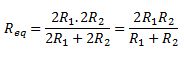
Therefore, the current I1 of this circuit will be:

Similarly, using this same method, we analyze two other circuits. The second circuits have all the heating elements connected in series as followed:

All in series


Circuit 3: All in parallel


By observing the equations above, we notice that the I3 will result in a current with the highest magnitude and therefore leads to highest working power of the from the heating elements.