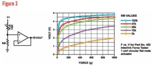
Week 8 the FSR’s came in. I connected one FSR to a simple voltage divider circuit to finalize how I will be differentiating between a ball and a person. I had an input voltage of 9V and an Rm value of 100K. The circuit shown below was used and copied from the data sheet.
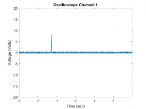
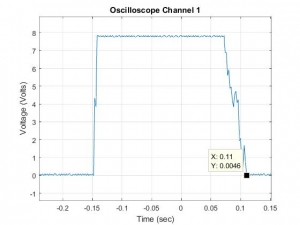
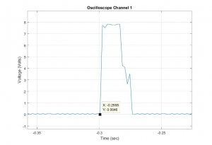
Above is the output signal of a small bounce from a volleyball. The sampling rate was set at 100 Hz on the oscilloscope for this data. A small bounce is the smallest impact the line would get. As you can see, the signal maxed out as expected. These FSR’s are extremely sensitive to high force.
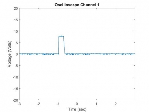
Above is the output signal of a running foot on the FSR. A run is the smallest duration of time a person could contact the line. Comparing these two extreme cases will help me officially decide how to differentiate between the two contacts. It is clear from comparing this figure to the one above that a ball contact is much shorter than the impact of a person. Therefore, duration will be the way to differentiate between the two contacts.
Looking a little closer at the signals, I need to test different scenarios to find out the exact duration of impacts. By increasing the sampling rate and using the data cursors on MATLAB, I was able to find the exact duration of the contacts.
Above is the output signal of a run. The duration of time a foot stays on the line is 0.258 seconds.
The above figure is the output signal of a small bounce. The duration of time a ball stays on the line is 0.026 seconds.
Below is a table of results from all of the different scenarios:
| Scenario | ΔT (seconds) |
| Bounce | 0.026 |
| Hard Hit | 0.038 |
| Soft bounce | 0.014 |
| Step | 0.516 |
| Run | 0.258 |
| Two Foot Jump | 0.612 |
Comparing extreme cases (the fasted player contact vs slowest ball contact) I can further conclude that time is the best way to differentiate between forces. A person contacts the line at least 10 times as long as a ball.
With this information I can now look more into the circuiting of the system. A microprocessor is easier to code when reading digital signals compared to analog. Because the FSR’s are so sensitive, the signal from the voltage divider basically outputs digital data. If I use a high value resistor (100k from the graph in the first image on this page), that will further confirm that the input signal to the Arduino will be digital. I confirmed this estimate with the following equation and different input scenarios:
With help from the data sheet, I have decided to use a voltage divider for each 2 foot section with the suggested LM358N op amp. The three FSR’s in the two foot section will be in series because the they are acting as one big resistor per sensing section. I will look into using FSR’s in parallel compared to series in the near future. The image below shows the preliminary circuit used for a two foot sensing section. This circuit design may be changed in the future.
