-

Senior Capstone Project
NYSID / Schenectady ARC Project Fabric Cutting Device Mac Anderson Union College Class of 2018 The goal of this project is to create a cutting table that the disabled employees at the Schenectady ARC can use...
Read More -

Cutting System

The cutting system for this project needs to be completely safe and operate efficiently. In talking to the owner of Tiddy Tots, if a cutting system like this was available to them, they would use it continuously throughout the day. This means that the cutting system will need to be durable and consistent over long periods of time. The cutter for this system will be a simple hand held rotary cutter that will be guided across the table on a rail system. A custom bracket must be made to hold the rotary cutter and attach it to the two guide rails on either side, which can be seen in Figure 1 below. Bearings will allow the system to glide back and forth across table with ease. Employees will be able to operate the system from one side of the table using the extension on top of the bracket.

Figure 1 Guide Rails
The bracket that will hold the rotary cutter will need to be custom made to fit the Gemsy Lejian YG-65 cutter. This bracket will be made in the mechanical engineering shop using the CNC machine. An example of this bracket can be seen in Figure 2 below.

Figure 2: Cutter Holder
Frame
The area in which this system will be placed in the ARC is about 10′ by 10′. For this design to work properly, all of the rollers and cutters must be parallel to each other. To ensure this, the cutter and rollers will be placed on a 80/20 frame instead of mounting it to a table. The base of the frame will be 3′ by 6′ and each roller will be mounted at a different height, which can be seen in Figure 1 below. The frame will be connected using internal connectors and each bar will have at least 2 connections to ensure the frame is sturdy.
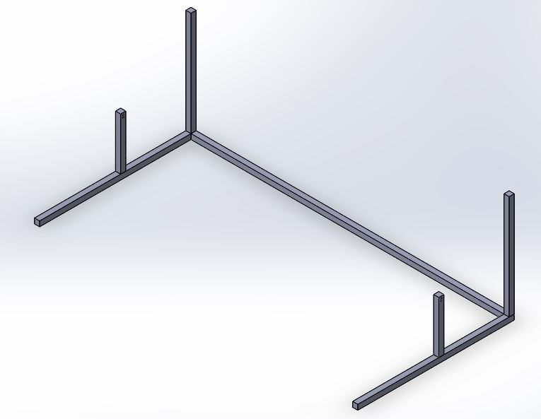
Figure 1 Frame Base
To ensure that the fabric is not slipping as it rotating around the roller attached to the rotary encoder, tension must be held on the fabric. This will be accomplished by using a tension system that can be adjusted to increase or decrease the tension of the roller holding the material. The roller attached to the encoder will be attached fixed at the base of this tension system, which can be seen in Figure 2 below. The tension roller will be mounted 1 foot above and can be adjusted to be closer or further away from the roller with the fabric on it. That roller will be mounted 2 feet above the base of the frame so that the fabric has to move in the downward direction as it moves towards the tension system.
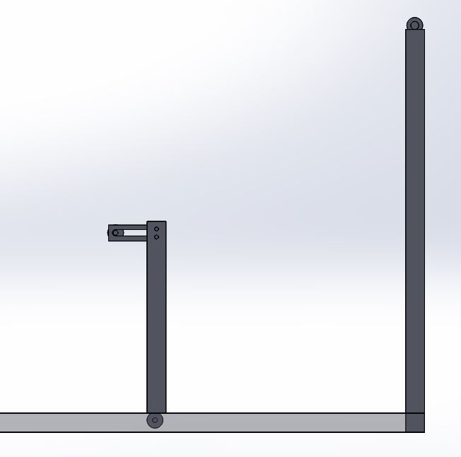
Figure 2 Tension System

After the tension system is set, it should not need to be adjusted until a new roll of material is loaded onto the system. Since the ARC will be cutting a variety of materials with different dimensions, the roller that holds the material before it is cut will need to be adjusted depending on the width of the material. For the system to work properly, the material must always be held on the operational side of the table. That is the side that the cutter and encoder outputs can be seen from. This means that the roller will need a lock that can be pushed towards the operational side of the table, holding the material in place. This locking system will need to be adjusted each time a new roll is loaded into the system.
Coding

The code for this system will be controlled by a Raspberry Pi mounted near the cutter. The Pi will take the input from the encoder to calculate the length of material that has been pulled out. This will be done by recording how much the roller has rotated and multiplying that by the circumference of the roller. For example, if the roller is only rotated half a rotation, the length of material will be equal to .5 x 9.45″ (circumference of a 3″ roller). The Pi will then output this calculation to the seven segment display. This will allow the employees to see the length of material they have pulled out in real time. This display will be reset every time a cut is made. A second seven segment display will be used to record the total length of material dispensed.
The Raspberry Pi will control the power to ensure that the safety guards are down before a cut is made. This will be done using break beam sensors mounted on the cutting system. One break beam sensor will be mounted on the operational side of the table near the side guards of the cutter. The reciever for this break beam will be attached to the guard so that when the guard is down the beam will not be broken. Therefore when this input to the Raspberry Pi is a “0”, meaning the beam is not broken, the Pi will allow power to the cutter.
A second break beam will be placed on the other side of the cutter. This sensor will detect when the rotary cutter passes across the table, telling the Pi that a cut has been made. When the beam is broken, indicating a cut has been made, the Pi will reset the first seven segment display.
© Union College.
All Rights Reserved.
Designed by Elegant WordPress Themes | Powered by WordPress