XBee Relay Test

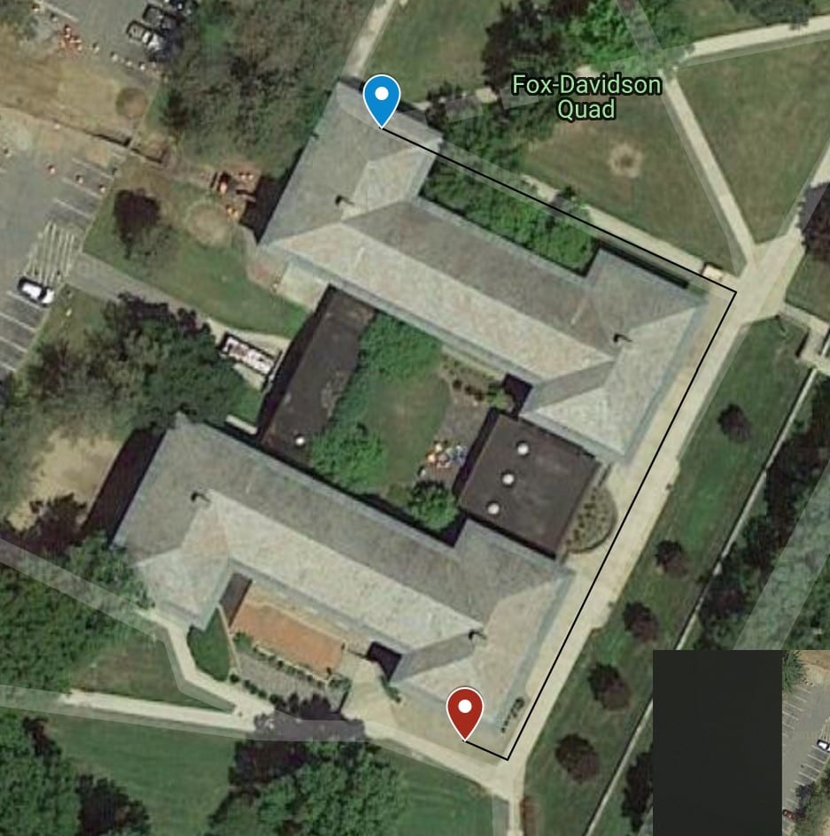
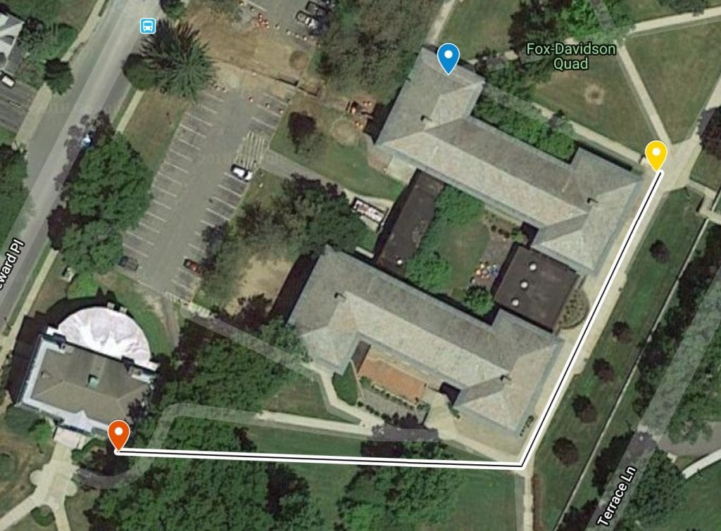
Using this wonderful guide made by Digi, I configured a simple relay network of three XBee Pro 538 modules. This used their XTCU configuration software so program the radios to be part of the same network. The transmitter and receiver were first placed out of range, then the relay was placed in a spot that provided communication between them. This test used broadcast messages, so my next work is to design some simple Arduino code to send unicast messages that are addressed only for the receiver, and get relayed by the relay node.

The XBee API makes it simple to send messages to any node in a network as there is no master/slave designations. This will allow the relay node to also send messages to the transmitter or receiver, such as telemetry or connection quality.

Outdoor Control Relay Tests

I conducted a test outdoors with and without the relay.

The transmitter (ground station) was placed under the overhang (blue marker) at the entrance to Davidson North. The overhang I believe should restrict it from transmitting over the building and restrict the reflections off of Fox that could bounce over the building.

Signal was lost immediately after turning the corner of the building (red marker).

I placed the relay at the corner closest to the ground station (yellow marker). Signal was lost significantly further than without the relay. There were spotty points on the way, but it remained relatively strong until it cut out completely right by Webster.


The test confirmed that the relay does fulfill its base function. I would like to conduct a test somewhere with less places for reflection. The terrace wall probably made this test not as accurate as it could have been.

Start of 2019: Functional Control Relay

Functional Control Relay

As a first order of business, I assembled the basic relay as the last part arrived right before the end of last term.

The PPM output of the FrSky X4R was input into the DJT module’s PPM in. Using a forum post, I determined the pinout of the module. The DJT module doesn’t have listed power specs, but I took an educated guess and powered it with 5v, which seemed to do the trick.

I tested the system using a servo plugged into the “end” receiver and it worked as expected!

Week 10 Notes

Field testing:

RSSI: Test at the longest range in a line between the two points already taken

Relay testing:

Distance would work fine if not for an obstacle, relay allows communication not because of range extension

Email Lisa about last part

Educated guesses for parameters

RSSI Plots

RSSI Plots

The data is certainly noisy, but with a reasonable moving average it is discernible which antenna is receiving a stronger signal over the other. It is much easier to tell with a larger angle between the antennas which is to be expected.

Indoor Relay Tests

I conduced a simple indoor test by leaving the “UAV” transmitter in my room, walking down the hall into a friends room where I could no longer receive signal directly from the “UAV,” then set up the relay right outside his room in the hallway and switched my “ground station” receiver over to receive from the relay. The signal was relayed perfectly.

Week 9 Notes

Plot data

Plot average as a line

Plot ~1/10th second running average

All on same graph

Looking for smallest length of time that gets as close to the avg as possible

Ask Lisa about transmitter

Range testing

Turn the mountain sideways

Look for somewhere that will give consistent blockage