The BSE detector is mounted in a ring at the bottom end of the conical SEM pole magnet. It’s highly vulnerable and can be broken by samples being raised (Z direction) or tilted. WATCH WHAT YOU ARE DOING!
The BSE detector has several operating modes. It’s divided into five active segments: four are in 90° pie slices around the electron beam aperture, and the fifth is on the far side of them. The four segments can be turned on to produce standard backscattered electron images, or one or more can be turned off to give shadowing 3-d effects, somewhat like the SE detector. Alternatively, the fifth, back segment can be turned on to give slightly more sensitivity, plus a 3-d shadowing effect. The shadowing is strongest if only the back segment is on, though sensitivity is less. Because the signal for BSE imaging is simply the total energy of electrons hitting the detector, a single variable, images are just a gray scale. Parts can be colorized using 3rd party software. The total energy of backscattered electrons that reach the detector depends on beam voltage, beam current, and the mean atomic number of the material under the beam (the higher the atomic number, the more backscattered electrons). Careful contrast enhancement using screen controls, and sufficient electron beam power, can give nicely contrasted images for regions having mean atomic number differences of <1 AMU. Differences in grain orientation can sometimes be seen as well.
Beam currents should generally be higher for backscattered electron imaging than for secondary electron imaging. A good place to start is around 10 nA with the detector gain set to “high”, which also happens to be a good current for X-ray analysis and mapping. Most backscattered electrons come from relatively deep in the sample (a few microns). Because the electron beam scatters more at greater depths, this results in poorer resolution than can be obtained with the SE detector, which is typically also used with much lower beam currents. To improve BSE image resolution, reduce the beam voltage (even to below 1000 V) and increase probe current or detector gain as necessary. BSE image resolution degrades much faster with higher voltage (larger volume from which BSEs come) than higher beam current (larger beam spot size). See Richards et al. (1999). Note that this is the reverse of the situation for SE imaging, where high voltages (small electron wavelength) and low probe currents (small beam spot size) generally give better resolution.

The BSE detector is seen edge-on, at the tip of the SEM pole magnet. It is actually a flat silicon chip with electronics and a holder behind it. From simple geometry it should be obvious that detector sensitivity will increase the closer the sample gets to the detector (shorter working distance). The detector is very fragile! Very easy to break! Very expensive! Watch with the chamber camera (as seen here) while raising or tilting the stage!

Zoned zircon crystal in biotite, hosted in a biotite granite. Note that the contrast has been stretched to emphasize zoning in the zircon, rendering the host biotite black.

Biotite surrounded by quartz and feldspar in a biotite granite. The darker gray streaks in the biotite, parallel to the cleavage, is secondary chlorite. White crystals are apatite (note faint zoning in the big one), and the surrounding darker gray crystals are quartz and feldspar.

Zoned titanite crystal in plagioclase and quartz, hosted in a biotite granite. Note that contrast stretching has been used to enhance compositional zoning in the titanite, rendering the host plagioclase and quartz black. The white grain to the left is magnetite.

The grain to the lower right is plagioclase, an inclusion in a large K-feldspar crystal. K-feldspar, to the upper left, contains dark-gray albite exsolution blobs. The plagioclase margin, near the plagioclase–K-feldspar contact, is darker and more mottled than the rest to the lower-right. The darker margin is albite that crystallized late, whereas the lighter gray plagioclase is more calcium-rich. The mottling of the rim albite shows that it has variable chemical composition. This is in a biotite granite
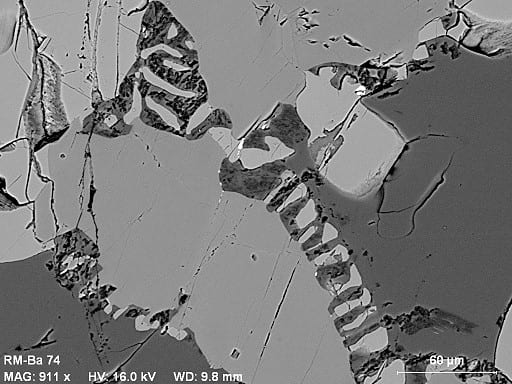
This shows small-scale reaction textures in a pyroxene-bearing amphibolite. The large dark gray grains are plagioclase, medium-gray are hornblende, lighter gray are orthopyroxene, and the tiny bright white specks are ilmenite. The grungy material between the small orthopyroxene ‘fingers’ includes K-rich white mica. This is an odd metamorphic subsolidus reaction texture that probably involved early hornblende dehydration to form the fingers, and later hydration of feldspar between the fingers to produce the white mica.