2/20/15
This past week I have made progress with the GPS, a new Time of Flight sensor, EEPROM memory, and system robustness. I was able to use serial communication to access the GPS NMEA information with my computer. Below is an example of the NMEA sentences recovered from the GPS using the program puTTY.
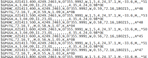
Figure 1: NMEA sentences recovered from College Park Hall.
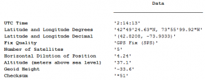
Figure 2: Fix Information (GGA) sentence information made clear using MATLAB.
I wrote a MATLAB script to decode the sentence information and make it more understandable to the user. The GPS latitude and longitude information was accurate. When I entered the information into Google Maps it was able to find the spot in which I was working.

Figure 3: Google Maps with GPS location data.
This confirms that the GPS is function correctly and that the problem I am having is a problem with the I2C protocol communication and not a broken sensor. When I tested the GPS using I2C I received zeros for the location data, even though I had not reset the GPS after getting the information Serially. Now I need to use a logic analyzer to see what is actually being sent and received between the Arduino and GPS.
Last week Professor Hedrick introduced me to a new Time of Flight sensor, seen below, that measures distance using IR and the time it takes for the reflection to return to the sensor.

Figure 4: VL6180 Time of Flight sensor.
The VL6180 is designed for I2C and operates between 2.8 V and 3.3 V and returns the range to a target (like a wall or floor for example). The datasheet claims a maximum distance of 25 cm and does not specify a minimum range. I was able to use this sensor successfully and obtain distance, in mm, to target. I found that under low light conditions (no lights on in the lab, just the sunlight from the windows) the range was about 15 cm, however, there is a gain function in the sensor and this can be used to boost sensitivity. I have not yet messed with the gain setting in the sensor, which is controlled with I2C, because under decent (lights on in the room) lighting conditions I was able to get results up to 25 cm. This sensor can be mounted on the bottom of the plane and help determine when the plane takes off and lands. The bottom of the fuselage to the ground is about 7-8 cm which is well within the range of the sensor.
This week I integrated the EEPROM chip into the main telemetry system. This chip also uses I2C protocol and was relatively simple to use. Now the Hornet telemetry system has 32KB worth of space which is equivalent to about 20.5 minutes at a system sample rate of 1 second (system sample rate is defined as the time it takes to gather one sample of each data type). Even at a system sample rate of half a second (about 10 minutes of data) there is still plenty of space for an entire flight’s worth of data since an average flight is about 2.5 to 3 minutes (by watching footage from last year’s competition).
Lastly, an improved sketch allows the system button to start and then stop the data recording without corrupting data or causing indirect errors and uses flags to mark the end point. The system will be able to transmit live altitude data to the ground station. My goals for the next week are to practice my demonstration and make sure that the system operates correctly, practice my oral presentation, finish the poster board, and record my video demonstration. The GPS is the last primary goal that needs to be met for the system. After the GPS sensor works with I2C I will then focus of improving system robustness and repeatability.
Recent Comments