As the propulsion engineer, my responsibility within the team lays in the design and implementation of an electric propulsion system.
Due to the success of last year’s team, exploring other electric motor and electronic speed controller combinations was deemed unnecessary. This year’s aircraft, same as last year’s, will utilize a brushless motor that is manufactured by O.S. Motors and is rated at 1110W. The selection of a speed controller was based on its compatibility with the motor and power rating. This year the aircraft will operate under the Castle Creations Talon 90, which is one of the motor controllers that is recommended by Neumotors for use alongside the 2015 SAE Power Limiter.

The SAE Rules state that all electronic components on board the aircraft must be power by a commercially available 6s 22.2 volt Lithium- Polymer battery, where the minimum requirement of the battery is 3000 mAh @25C. However, it is unclear as to which battery rating will provide the aircraft with sufficient energy to last a flight round. After watching footage from last years’ competition it was determined that each flight round lasts between one to two minutes. It was important to find a battery that would provide the plane with enough energy to complete a three to four minute flight near max power. A 4000 mAh @30C E-Flite Li-Po battery (shown below) was initially purchased to initialize the propeller-testing phase.

To test different APC electric propellers, a test bed, left behind by a previous Union College Aero team member, was used. The propeller along with the motor and all other electronics were mounted on the test bed as seen in figure below . The overall goal was to determine which propeller would provide the aircraft with an optimal amount of thrust while maintaining a power level below the 1kW limit.
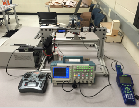
Test Bed Set up
The forward force (thrust) produced by each propeller was measured by using a combination of an Xplorer GLX Graphing Data Logger and a PASCO® Dual Load Cell amplifier. Additionally, all electric measurements were were recorded using an oscilloscope and a Hall effect sensor. The Hall effect sensor was used to accurately measure the current being drawn from the battery. Having thrust and power data for each APC electric propeller provided the team with sufficient information to choose the optimal propeller. The following table shows all the propellers tested near max power.
Note: Click the link provided below to view a video that will provide some insight to how a propeller was tested.
https://www.youtube.com/watch?v=R_0TYl_uX90

Propeller Thrust Test Data
After extensive testing the 18x8E propeller was chosen because it consistently provided the most thrust near max power. Notice that instead of looking at how much thrust a propeller provides at full throttle, the focus was on how much thrust it provided near max power. This is due to the fact that all the propellers listed in the table above engaged the limiter at different throttle positions. In addition to being the top thrust provider, the 18x8E propeller was also selected because it engaged the limiter at a higher throttle position (position 1.5), where as the others engaged the limiter before reaching half throttle.
Each throttle position (hash on the throttle joystick) corresponds to a different width in the PWM signal that gets sent to the electronic speed controller. In R/C planes it is standard for the control signal to be PWM signal, where the width of the signal translates to a desired RPM. If we let the center of the joystick then the throttle position ranges from -3 t +3. The transmitter we are using sends a PWM signal that ranges from 1ms -2ms as shown in the figure below, where 1ms corresponds to the lowest throttle signal and 2ms corresponds to the highest throttle position.

PWM Widths of Control Signal
It has been repeatedly stated throughout the SAE forums by officials that in order to prevent the limiter from engaging, teams should design their power system so that it only utilizes power values below the limiter setting at full throttle. With that in mind, in order to prevent the limiter from engaging, the throttle travel adjustment within the transmitter will be adjusted so that even if the pilot ramps up the throttle joystick, the power being drawn from the battery will never exceed the 1000W threshold. This, by no means, is the best solution to avoiding tripping the limiter, but unfortunately due to the ban of additional electronics within the circuit path it is difficult to avoid such issue without modifying the control signal being sent from the transmitter.
The reason why this approach is not an adequate solution is because changing the travel adjustment of the throttle within the transmitter limits the control signal to specific PWM width. The width you limited the control signal may be the max width you can go before tripping the limiter at a fully charged battery, but as time elapses the voltage of the battery decreases, which causes your initial limit to increase, but since the throttle is clamped to the initial limit the pilot won’t be able to compensate for the power loss by increasing the throttle, which renders your power system no optimal.
The following figure displays a sample of the raw thrust and power data collected for the 18x8E propeller .

18x8E Prop Data
The figure above shows the raw data collected for the 18x8E propeller as well as its 5 point windowed average. Taking a windowed average allowed me to determine that as long as the windowed average power doesn’t go over 1000W for more than .4 seconds the limiter will not engage.

Limiter Effect
The figure above shows the effect that power limiter has to the overall system. From the figure we can clearly see that there is a significant reduction in thrust when the limiter engages. This causes the motor to stall and as you can imagine, if the motor stall while airborne it can ultimately lead to our plane crashing and end our participation in the competition.

Crashed P-1 Murcielago
The figure above shows the result of attempting to fly our first prototype. It is important to point out this was the result of a 5-10ft fall. One can only image how drastic the impact and effect will be if the plane were to hit the ground from a height of 100ft.
After determining that 18x8E propeller was the best option, the next goal was to determine whether or not there were other battery capacities that would provide the plane with sufficient energy to complete a three to four minute near max power. Finding the right battery played a pivotal role because any excessive capacity adds unnecessary weight to the plane. Any weight that can be removed the system is directly added to the payload the plane can carry. A 3200 mAh @30C E-Flite Li-Po battery was purchased to verify if the 4000 mAh battery initially purchased exceeded our needs.

After testing both batteries it was determined that they bot have enough energy to enable the plane to complete a three to four minute run as seen in the following figure.
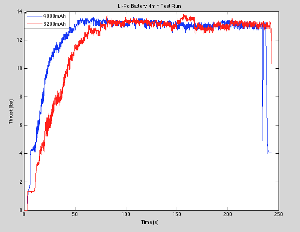
3200mAh vs 4000mAh Battery Comparison
During testing it was discovered that the 3200 mAh battery weighs 4 oz less, which reinforced the decision to go with the the 3200 mAh battery over the 4000 mAh rated one.
The final electric component selection is listed below:
- O.S Motors Brushless Motor
- Castle Creations Talon 90 ESC
- 3200 mAh @30C E-Flite Li-Po battery
Please take a look at the P.I Controller Section for information about my approach to prevent the limiter from engaging.
The following images were obtained using SolidWorks® and provide detail about the C-1 Murcielago that will be ruling the skies at competition.

Top View
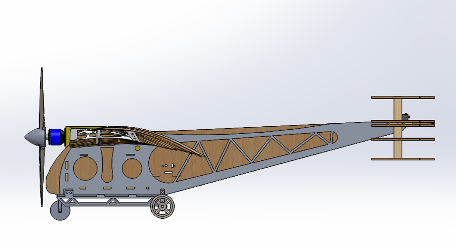
Side View

Over View
Recent Comments