UMOBILITY PROJECT
Construction Manual
Before starting the construction manual, please make sure to purchase all the parts from the parts list page. For additional information on wiring, soldering, crimping, or making connectors for cable, check out videos under the “YouTube Resources” section.
Dissembling Wild Thing
1. Remove the battery from the Wild Thing Device.
2. Remove the plastic cover that protects the Wild Thing circuit board.
3. Carefully remove the connectors/wires attached to the circuit board.

4. Remove the circuit board itself.

5. Unscrew the screws of the caps attached to the ends of the wheel axels. Be careful to keep the washers that comes with the caps. Once these caps are removed, the wheels should also be removed.
6. To remove the wheel protectors, unscrew each of the four screws attached that attaches the body of the Wild Thing to the wheel protectors.
7. Once the wheel protectors are removed, the two handles can be easily removed.
8. Reattach the wheel protector
9. Reattach each wheel and secure each of the wheel by putting back on axel cap with washer, as it was originally.
Assembly of Electrical Components
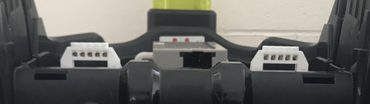
1. Attach the two terminal blocks on the edge of the Wild Thing base by drilling four hole and attach them with appropriate screws.
2. Carefully cut the motor wire right below the connector lead.

3. Strip off a quarter inch of insulation on each of the motor wire and extend the wire using button connector with heat shrink (see online resources section for YouTube videos)
4. For better protection, use a heat shrink tube to insulate the crimped connection (which was initially heat shrunk).
5. Check the motor side and power side of the spark motor controllers. Connect the first pair of motor wire on one side of Wild Thing to the motor side of the spark motor controllers. Do the same with the second motor controller with another pair of motor wires.
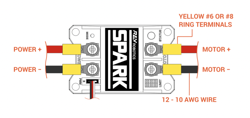
6. Connect the two Power + sides of the motor with a wire with attached crimped connector (you have to make this). Similarly, connect the two Power – side of the motor. The Power – should be connected to common ground, which is one the terminal blocks attached in step 1. Do not attach Power + to the terminal blocks, since it will be connected to the LED latching switch in later steps.
7. Now, take the battery plug and connect white wire to the other terminal block (not the ground terminal) to establish a railing for 12V power supply.
8. Connect the black wire of the battery plug to the ground terminal.
9. Drill a hole big enough to tightly fit the LED latching switch on the lower left surface of the Wild Thing base.

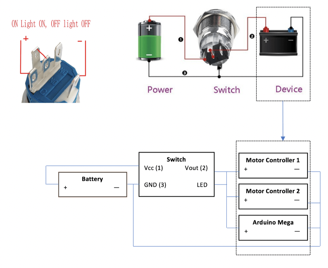
10. Using the diagram below, connect the switch’s “+” terminal (labelled “1” on the top right in the figure below) to the 12V terminal block, where the white wire of the battery is connected. Connect switch’s “-” terminal (labelled “3” on the top right in the figure below) ground terminal block, where the black wire of the battery is connected. The “NC” terminal (labelled “2” on top right the figure below) supplies power to the motor controllers and the Arduino Mega when the switch is on. Connect the “NC” terminal to the “Power+” of the motor controllers and to the red wire of the 5.5mm DC barrel plug, which plugs into the Arduino DC barrel jack. Connect the black wire of DC barrel plug to the ground terminal.
Making Cables for Peripheral Devices
Ultrasonic Sensor Cable
1. Using 22 AWG wires (one black, one white, and 1 red), build two 4-pin JST-XH connector housing (see Youtube Resources section). The two white wires should be in the middle.
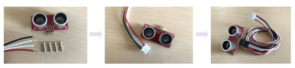
2. Cover the cable with a wire sleeve and shrink tube the ends of the sleeves. The completed cable should look like the following figure.
Ability Switch Cable
1. Using 22 AWG wires (one black, one white, and 1 red) build four ability switch cables. One side of the cable have a 3-pin JST-XH connector housing (see Youtube Resources section).
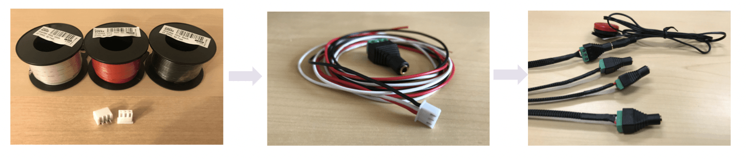
2. On the other side of the cable, the red, white, and black wires should be connected to the 3.5mm jack terminal block. The red wire should be connected to the “L” port, the white to the “R” and the black wire to the ground ports of the jack terminal blocks, as shown in the figure below.

3. Cover the cable wires with wire sleeves and secure the cable sleeve ends with heat shrink tubing.
4. The finalized cables should look like the following figure.

PWM Cable
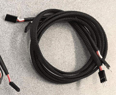
1. Spark Motor controllers come with a ready made PWM cable. To be consistent with other cables, optionally cover the two PWM cables with wire sleeves and secure their ends with heat shrink tubing.
2. The PWM cables should look like the following image.
Battery Plug
1. To be consistent with other cables, optionally cover the two battery plug with wire sleeves and secure their ends with heat shrink tubing.
Joystick Cable
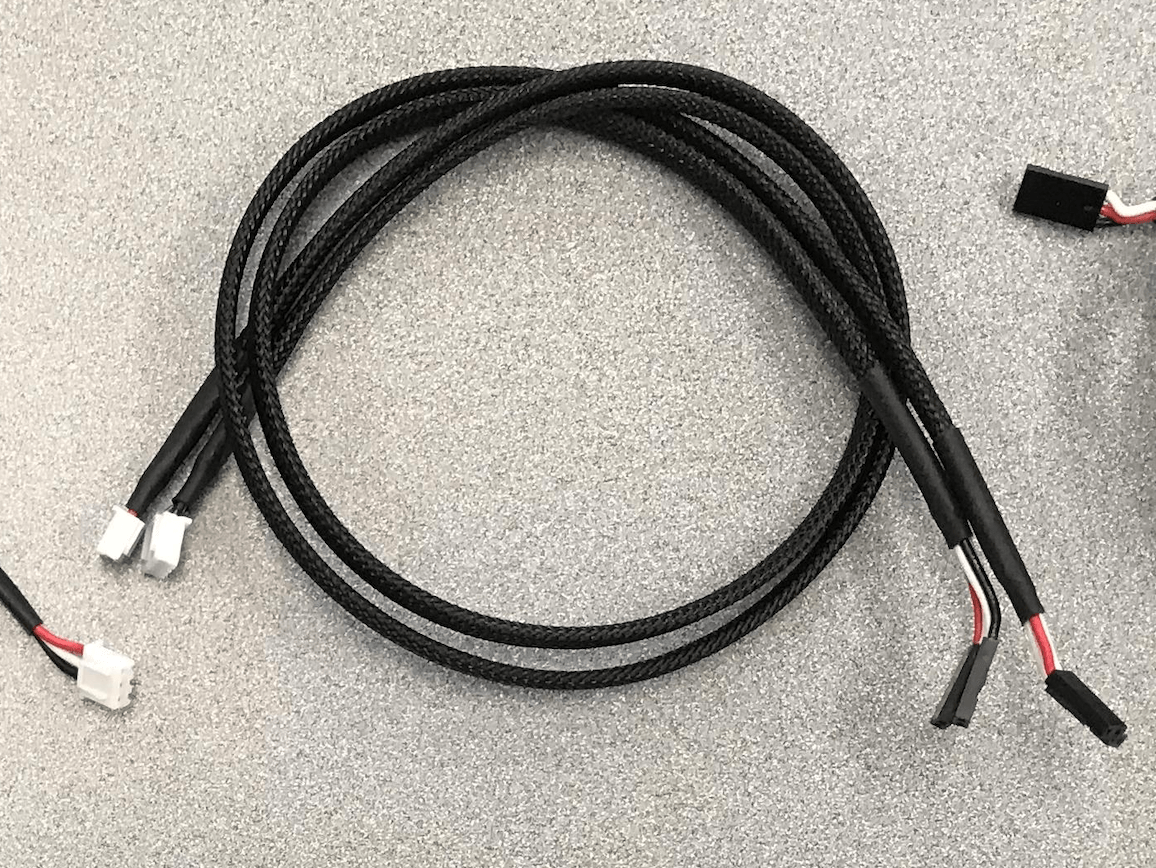
1. Using 22 AWG wires (two black, two white, two red), build a six-pin JST-XH connector housing (see Youtube Resources section) for the cable (see Ultrasonic cable section). The order of cable wire colors is red, white, black, red, white, and black.
Constructing the Breakout Board
Before building the breakout board, print out the complete pin out table as well as complete schematics, they can be accessed under Build Your UMobility section on the website menu bar.
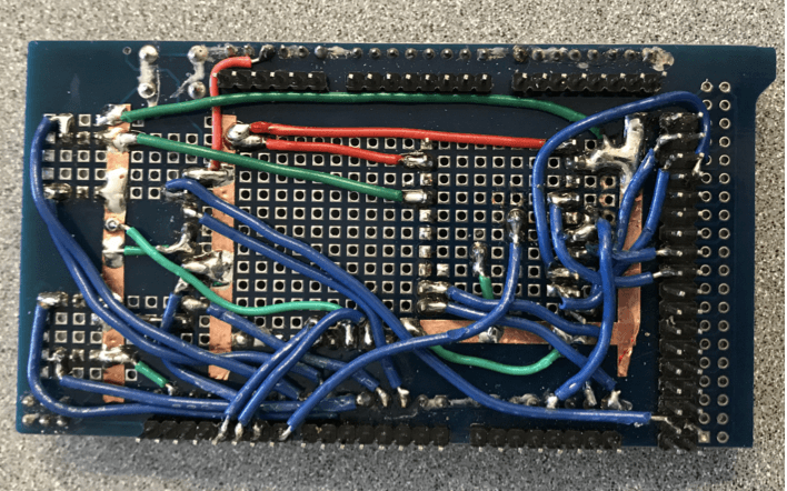
1. Take an empty Arduino Mega shield (image on the left), attach four 3-pin JST-XH connector housings (for four ability switch cables), two 4-pin JST-XH connector housings (for two ultrasonic sensors cables), two 10-pin female headers (for Gyroscope and Bluetooth module), two 3-pin male headers and a piezo buzzer on the Arduino Mega shield (see arrows in the image below).

2. Using the complete schematic diagram (go to the Schematic Diagram page), connect the Arduino Mega pins to their corresponding peripheral device cable housing and header pins by soldering (see Youtube Resources section)
3. Once the Arduino pins are connected, snap the cable plugs onto the breakout board.
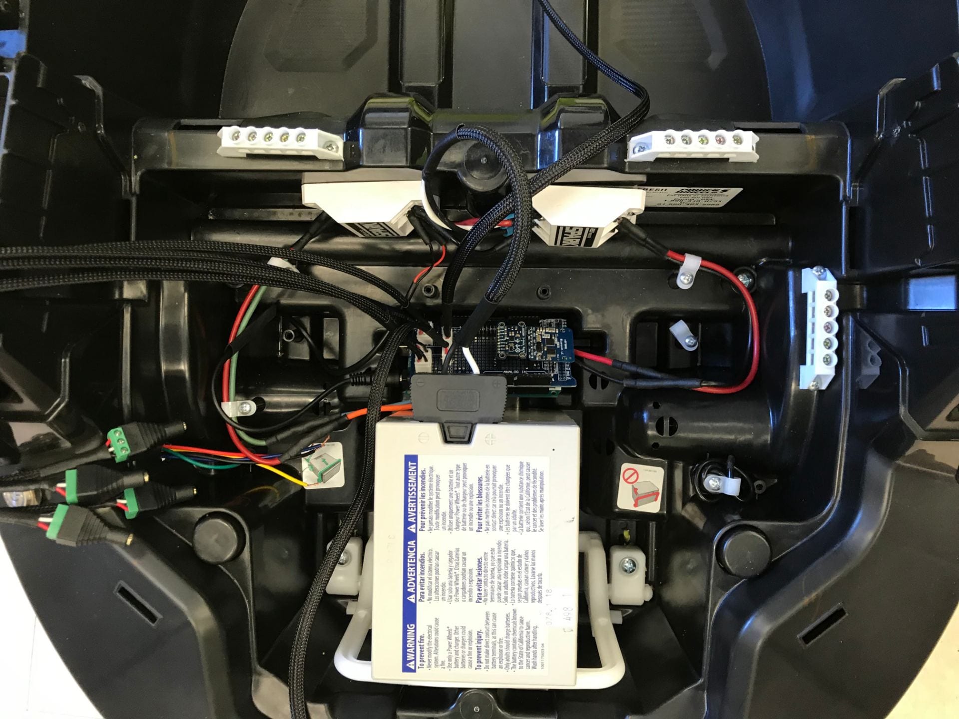
4. The control system is complete.
5. Before connecting the battery cord to the battery, finish the “Uploading Code” section first.
6. Then read the debugging page on the website. Once every test in the debugging section passes, proceed to putting back the battery into the Wild Thing battery compartment, plug the battery cord into the battery.
7. Press on the LED switch.
8. Assuming “Uploading Code” section is done at this step, gently operate the device via ability switches or joystick.
9. The control system should look as follows.
Youtube Resources
How to Make JST-XH Connectors for Cables
For detailed explanation, please watch this.
How to Use a Crimping Tool for Crimp Connectors
For detailed explanation, please visit watch this.
How to Connect Wire Using a Butt Connector and Heat Shrink
For detailed explanation, please watch this.
How to Solder Wires
For detailed explanation, please visit watch this.
How to Use Heat Shrink Tubing
For detailed explanation, please watch this.
Uploading Source Code
This section explains how to upload the source code onto the Arduino Mega.
1. Download and install the Arduino IDE here.
2. Open the Arduino IDE.
3. Download the source code from here. This github page can also be accessed by clicking the “Software” page on the website menu under “Build Your UMobility.”
4. Open the file UMobility.ino. At the top of the code, there is a section that will allow users to change the settings of the device. To activate desired settings, change the associate setting variable to true. To disable the setting, change the variable from true to false.
5. Double check if the pins defined on the code matches the pins wires on the breakout board.
6. Connect a USB cable to the Arduino Mega and then to the USB port of your computer.
7. In the Arduino program, go to Tools >> Board >> Arduino/Genuino Mega or Mega 2560

8. Click the “Upload” button. The code is now uploaded to the Arduino Mega.
