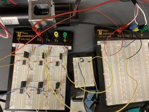
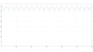
The driving system runs as expected. The AC induction motor moves continuously and as soon as power is provided when 24VDC is applied to the MOSFETs with a current draw of 0.62A. The output frequency of each of the three-phase AC signals is 50Hz and they are 120 degrees phase shifted. Below in Figure 1 is the Simulink output of the inverter.
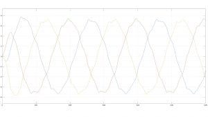
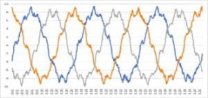
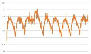
Below in Figure 2 is the actual output of the inverter circuit.
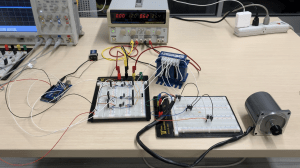
The DC machine could have been connected, but it was decided that the AC machine did not run as strongly as anticipated, so it did not seem necessary. Below in Figure 3 is the final driving system.
The braking system did not run as expected. The system runs continuously and as soon as power is provided, but it does not use real-time inputs. The code that was written for the rectifier circuit relies on the input starting perfectly at the beginning of a sine wave period, which is inconsistent with using a real-time input. The three-phase AC power was not fully converted to DC power, so a power resistor was not powered. Below in Figure 4 is the Simulink output of the rectifier.
Below in Figure 5 is the actual output of the rectifier circuit.
The actual output does not accurately depict what the output should look like, because the code was written for a perfect input, which is not realistic. Below in Figure 6 is the final braking system.