There are three places where antennas are needed, and also three frequencies. The diagram below lays out the links that the basic system will use:
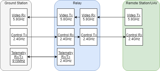
The links from the ground station to the relay will, to start, be over a fixed length and more-or-less stationary once the relay drone is in position. Tighter beamed antennas can be used on both sides for this. The links between the relay and the remote station/uav cannot be assumed to be fixed as the relay will not know the exact location of the remote station. The operators, however, are presumed to know the general bearing of where the remote station/uav is, so the relay can use antennas that have ~180° patterns. The remote station/uav has no knowledge of where the relay is, so it must use omni-directional antennas.
Antenna Types (that will be considered):
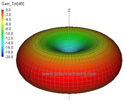
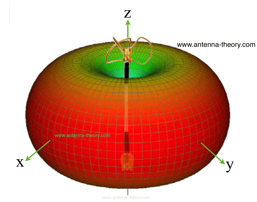
The three non-directed antennas are the monopole, circularly polarized cloverleaf, and pagoda. All three have good horizontal patterns, but the pagoda has a superior vertical pattern. In my application, the remote station/uav should never be directly above/below the relay, but it is still good to allow for it being close.
The two directed antennas are the helical and patch. The helical has a focused pattern, depending on how many turns. The patch is wider.
Choices:

The antenna choices focused on what is likely to be the limiting signal: video. Seeing documentation of long-range FPV flights online and first-hand, the video signal is almost always the limiting factor. The choice to use all monopole on the Control rx/tx is also due to the permanently installed monopole on the Ground Station tx and the included monopoles on all the other tx/rx for control. Also due to their lower frequency and well-made frequency hopping algorithms, control is generally not a limiting factor in signal range. The telemetry transmitters have the lowest frequency of all, and also only need to transmit around 400ft, not a problem at all in my experience.
A helical for the ground station was chosen as the relay will be in a set place once it is in the air. The helical can be pointed at the relay once and left there. A patch could likely be used, or even a non-directional antenna, but using a directional antenna gives the best possible signal. A pagoda on the relay video tx allows for good transmission directly downwards and flexibility in the rotation of the relay with respect to the ground station. A patch on the relay video rx will necessitate the remote station/uav be in a roughly specified area, but it is reasonable to assume this will be known. The relay can be pointed using yaw in the general direction of the remote station/uav. A pagoda on the remote station/uav will benefit the uav application more, but is a good all-rounder (literally) in terms of radiation pattern.
Parts list:
Quick RSSI test:
I soldered wires to the two RSSI pins of the receiver modules inside my diversity receiver. I also attached a ground wire after realizing I had neglected to do that… Using my Particle Photon (internet-enabled arduino) I made a quick test program to stream the raw values of the analog pins to serial. This is a quick test of no signal source near, then moving a very weak signal source very close to the antenna (my race quads video tx in pit mode):
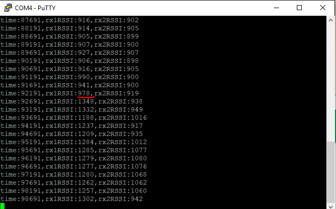
I added a red line between the changes. This is only a proof of concept currently and I need to map the raw A2D converter values to the percentage of connection they represent (0 – 100%). I also need to create a python script to log the data, or borrow a data collector from the ECBE dept. and log to Matlab.