Initial RSSI Tests

RSSI Testing

I conducted some basic RSSI testing at Maalwyk park. Managed to get two useful positions before the weather didn’t cooperate anymore.

This was my initial testing plan:

I started with the far right corner, and it promptly started to rain so I only managed to get the far right point. Both points are ~35 degrees off the centerline and ~800 feet away from the receiver.

I conducted 6 tests in total. One with no transmitter, one with the transmitter one yard in front of the receiver, both run for 45 seconds, and two for each side of the field with the antennas at 60 and 100 degrees, run for 2 minutes. The results are below:

The data, taken with a grain of salt as I don’t have enough points to make a real conclusion, shows that in general there is a detectable difference between having a transmitter on the different angles from the receiver, and the difference is larger with a larger angle between the antennas. This isn’t really a useful conclusion, but the test itself proves that I can collect useful data and it can be done fairly quickly.

Parts Arrival:

Everything but the FrSky DJT module has arrived.

I can now test the video relay in its entirety as well as start developing on the XBee radios.

Week 8 Meeting Notes

Radio tests:

Check strength is going down as square of distance (inverse square law)

Antenna angles:

Angle 90-105 for localization

Look up radiation pattern

Optimization between distance and angle resolution

Remove transmitter from quad

Check mouser order time

(Not-so-useful) Proof of Concept for Antenna Tracker

SRG Parts

I have submitted a parts list to Lisa as of Tuesday night. Most of the parts have short shipping time so hopefully by next week I can start to assemble and run actual tests of the first level of relay using just off-the-shelf components.

Antenna Tracker testing

I now have a complete setup to begin running tests of RSSI differences between two helical antennas. I attempted to run a proof-of-concept indoors (yes I know you told me specifically not to do that, but it was raining outside and I procrastinated. So I guess I have no real excuse…). The values were noisy, but it was easy to see that the RSSI output reacted to which antenna the transmitter was near. I started off by using “pit mode,” a feature that greatly minimizes the tx power of the transmitter. There is no official power level other than “2-3 meters” so regardless it is very small.

Moving up to 25mW, I could still see a reaction when moving parallel to the two antennas which were angled about 30° from each other. I tested also with 200mW. I haven’t included any data because it was difficult to interpret live and I saw no way that I could get usable info from it because I was inside, and it was erratic enough to not be worth the effort.

Proper testing will be done this week outside on a field. I will carry my phone with me when moving the transmitter around to record a GPS track so I can easily correlate (or not correlate) RSSI data with position.

Near antenna tests

Didn’t get done.

2.4Ghz Shielding

Tinfoil? The internet says it works. They are always right.

A simple 3D printed enclosure lined with tinfoil on the inside would make for a cheap and easy shielding cover.

XBee

Aero has quite a few XBee radios that appear to be close to the same as the ones I am purchasing. If the order takes longer than expected I can use these as stand-ins but I doubt they will take longer than it will take for me to finish testing other components.


Antenna Options

There are three places where antennas are needed, and also three frequencies. The diagram below lays out the links that the basic system will use:

The links from the ground station to the relay will, to start, be over a fixed length and more-or-less stationary once the relay drone is in position. Tighter beamed antennas can be used on both sides for this. The links between the relay and the remote station/uav cannot be assumed to be fixed as the relay will not know the exact location of the remote station. The operators, however, are presumed to know the general bearing of where the remote station/uav is, so the relay can use antennas that have ~180° patterns. The remote station/uav has no knowledge of where the relay is, so it must use omni-directional antennas.

Antenna Types (that will be considered):

  1. Monopole
    Source
  2. Circularly Polarized Cloverleaf

    Source
  3. Helical
    Source
  4. Patch

    Source
  5. Pagoda

    Source


The three non-directed antennas are the monopole, circularly polarized cloverleaf, and pagoda. All three have good horizontal patterns, but the pagoda has a superior vertical pattern. In my application, the remote station/uav should never be directly above/below the relay, but it is still good to allow for it being close.

The two directed antennas are the helical and patch. The helical has a focused pattern, depending on how many turns. The patch is wider.

Choices:

The antenna choices focused on what is likely to be the limiting signal: video. Seeing documentation of long-range FPV flights online and first-hand, the video signal is almost always the limiting factor. The choice to use all monopole on the Control rx/tx is also due to the permanently installed monopole on the Ground Station tx and the included monopoles on all the other tx/rx for control. Also due to their lower frequency and well-made frequency hopping algorithms, control is generally not a limiting factor in signal range. The telemetry transmitters have the lowest frequency of all, and also only need to transmit around 400ft, not a problem at all in my experience.

A helical for the ground station was chosen as the relay will be in a set place once it is in the air. The helical can be pointed at the relay once and left there. A patch could likely be used, or even a non-directional antenna, but using a directional antenna gives the best possible signal. A pagoda on the relay video tx allows for good transmission directly downwards and flexibility in the rotation of the relay with respect to the ground station. A patch on the relay video rx will necessitate the remote station/uav be in a roughly specified area, but it is reasonable to assume this will be known. The relay can be pointed using yaw in the general direction of the remote station/uav. A pagoda on the remote station/uav will benefit the uav application more, but is a good all-rounder (literally) in terms of radiation pattern.

Parts list:

  1. Video tx/rx patch
  2. Video rx helical
  3. Video tx pagoda


Quick RSSI test:

I soldered wires to the two RSSI pins of the receiver modules inside my diversity receiver. I also attached a ground wire after realizing I had neglected to do that… Using my Particle Photon (internet-enabled arduino) I made a quick test program to stream the raw values of the analog pins to serial. This is a quick test of no signal source near, then moving a very weak signal source very close to the antenna (my race quads video tx in pit mode):

I added a red line between the changes. This is only a proof of concept currently and I need to map the raw A2D converter values to the percentage of connection they represent (0 – 100%). I also need to create a python script to log the data, or borrow a data collector from the ECBE dept. and log to Matlab.

Flight Tests

I conducted two flight tests, one with a 660g payload (a second battery) and one unloaded. Arducopter logs an incredible amount of data for every flight, so I can see clearly how the current draw varied in different flight conditions.

Weighted:

The hover current was ~22 amps with a peak of 56 amps at full throttle. The peak current is well within the C rating of the battery I will be using, but is good to know for future battery purchasing options as the current battery I have is overkill on C rating, meaning its not a very weight-efficient choice for me (25C * 6.6Ah = 165 amps continuous draw!!!).

This result does not agree with the Ecalc numbers. Ecalc predicted a total current of 27 amps at hover. I am glad that the experimental numbers came out lower than the theoretical numbers, but it still might indicate a calibration problem with the current sensor. Luckily, the current sensor allows Arducopter to calculate the capacity used. This is shown in the bottom right of the first graph in the battery low warning as 2130mAh. The charger I use displays the capacity that it puts into the battery after a charge, so I can compare the two numbers and see how far off the Arducopter calculated number is from the chargers number.

The charger reported 2740mAh put back into the battery. That is a sizable difference and much larger than errors from efficiency. This capacity, with a 6 minute flight time, gives an average current of ~27 amps, much closer to the Ecalc estimation. This confirms that I will need to adjust the current detection parameters to get the correct amp rating.

Unweighted:

The unweighted hover was ~14 amps. This is closer, but still off, from Ecalc’s estimate of 17 amps. This flight was cut short so I couldn’t get a practical hover time, but the final current usage was only 1567mAh for a 6 minute flight. This gives a theoretical max flight time of 25 minutes, much higher than I expected. I expect my load to be much less than the 660 grams of the weighted test so this bodes well for long flight times with the relay equipment attached, even with the needed adjustment in current detection.

Height:

I conducted a simple altitude “test” as I had never flown my quad at heights exceeding ~75 meters. The legal limit is 400ft, or 122 meters. The quad did just fine ascending to the height and maintaining it. I foresee no issues with it dealing with high altitudes on calm days. Windier days may be more challenging. I also need to look into the geofence failsafe options I have to prevent a flyaway.

Discussions with Prof. Wong:

I had a meeting with Prof. Wong to discuss his experience and see if he had any tips or tricks for me regarding the antenna tracker. He believes that using RSSI is possible, but won’t be accurate at all. This was expected, but still pushes me to consider alternates, like a phased array as he discussed. I am also thinking of the complexity that this all adds and is only really needed in the range extender mode. An antenna tracker in relay mode is not necessary.


XBee Resources

While I wait for a decision on my SRG which was submitted September 20th, I am left to do as much testing as possible without having any parts.

Preparing XBee resources

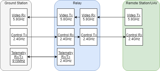
The XBee radios have many mature libraries, and plenty of examples and guides available for Arduinos, which I will be using to control the trio of radios in the relay system.

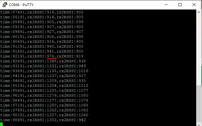
The main library is located here: https://github.com/andrewrapp/xbee-arduino/tree/master. It includes in its wiki a great getting started Developers Guide. The guide points out that the XBees can operate in two modes, AT or API. In AT mode, the radios operate basically as two ends of a hose. Bits go in one side, bits come out the other. There is little else to it. AT mode allows for fast transmission and the ability to implement a custom protocol. in API mode, the radios use packets to format data and address it to specific radios. This allows for better insight into RSSI as well as checking for errors, etc.

Packet mode makes sense for my implementation as I am sending discrete chunks of data from one side to the other. Some of this data may need to be sent more frequently than others, for example prioritize control data over telemetry data, and packets would make it simple to prioritize which data gets sent.

Quadcopter weight carrying test

I still have a good amount of time before aerial tests will be conducted, but the carrying capacity of my quadcopter is still an unknown. Theoretical calculations from ecalc.ch give 1.7kg, or about 3.7lbs, of payload capacity. Those numbers are what the quad can carry at the very maximum, meaning the max it can hold and still manage to get off the ground. The payload for a workable flight time must be as small as possible.

A payload of 2lbs brings the theoretical flight time down to 10 minutes, which is serviceable. The payload should be kept below this number as a general rule. I will refine the number further once testing is done.

Antenna tracking options

Hardware:

Antenna tracking will become a large factor if and when the range extender capability is introduced. It would also make ground station setup easier as antennas wouldn’t have to be manually aimed. As I have access to a laser cutter and 3D printer through the Makerweb, I will design and build the tracker myself.

There are plenty of DIY tutorials online:

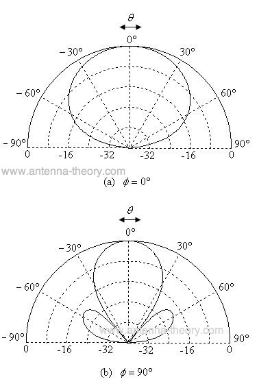
I am most interested in a by-default RSSI tracker and the possibility of adding GPS to its tracking capabilities. In both the “off-the-shelf” and XBee configuration, accessing the GPS location of the relay should be fairly straightforward. The code for an RSSI tracker could be modified to use GPS to establish an initial fix on the relay, then maintain a strong signal with RSSI. An algorithm to decide which method of tracking to use will be an interesting bit of research. This guy seems to have done something very similar to what I am looking for.

Software:

Unlike the software running the relays, the antenna tracker has the benefit of being ground based and larger sources of computational power. The tracker will have two data inputs: GPS location of relay (and it’s own fixed position) and one to two sources of RSSI. It’s output will be the bearing and angle of the antennas.

A simple tracker uses RSSI or GPS only. The this guy link from above has a very nicely organized GitHub repo. I initially thought that his project included combined GPS/RSSI tracking, but it appears that it does not. Combining the two data sources has the potential to make a very fast and reliable tracker. A basic operation pseudo code is shown below:

 RSSI_GPS_Track:
if RSSI is below signal threshold:
  point antenna towards GPS
else if RSSI above signal threshold:
  continue to track with RSSI

This would allow for very quick setup times as the tracker would not need to be manually aimed or scan back and forth until it picks up enough RSSI signal. It would also make the tracker resilient to a fast moving relay (not that that should happen) or to an obstruction obscuring the relay from the tracker. The tracker would not halt when signal is lost, but instead keep pointing at the general GPS position of the relay until signal is picked up again. This is already much more added functionality when compared to individual data sources, but there should also be more functionality with a better algorithm.

Other situations where this might come in handy:

  • Rejecting other signals that create “false” RSSI readings
  • Signal path reflections?
  • Very weak RSSI
  • More?

An algorithm that can use both sources, assign them a “reliability” index of sorts, and then decide which source to trust more would accomplish the goals of the simple tracker while also adding the above functionality (hopefully).

I have the option of writing my own algorithm, but I’m sure there are algorithms out there that do this, its just a matter of figuring out the right search terms. Here are some that I have found:

  1. Automatic Weight Learning for Multiple Data Sources
    when Learning from Demonstration
  2. (emailed Matt for help with search terms)