For my senior project I have designed an active control system that monitors and adjusts the power being utilized by the propulsion system before the SAE Power Limiter gets the chance to do so.
The following figure shows the block diagram of the propulsion system that was integrated in last year’s aircraft.
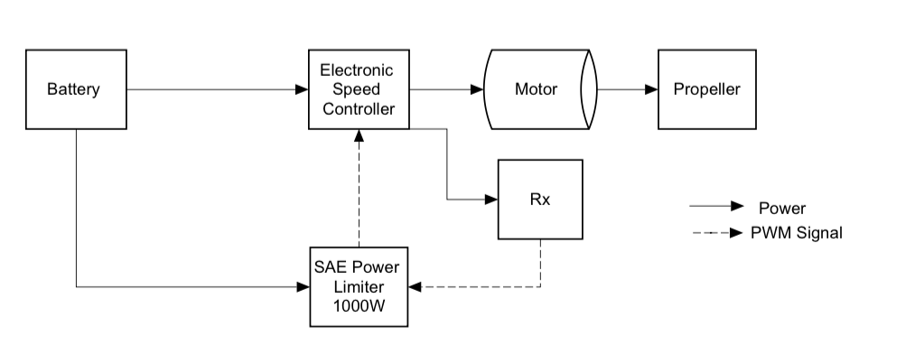
2014 Electric Propulsion System Block Diagram
The limiter is strategically place between the ESC and the battery so that it can monitor the power being drawn from the battery. The limiter is designed to even out the playing field by forcing each competitor to perform under the same power constrains and penalize any teams that exceed the 1000W threshold.
The following figure shows the block diagram of the electric propulsion system of this year’s aircraft.
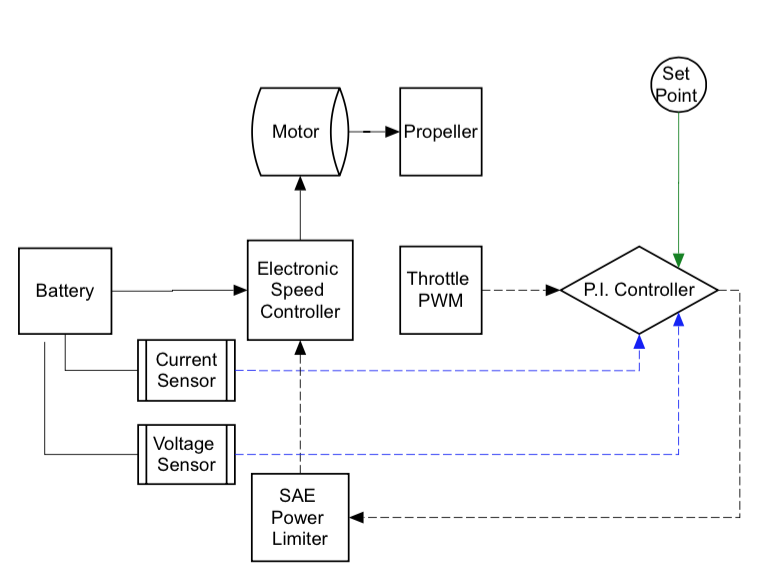
2015 Electric Propulsion System Block Diagram
This year’s system has three additional components: a current and voltage sensor as well as the P.I Controller. in the diagram, a solid black arrow indicates a power signal, a dashed arrow a PWM signal , a blue dashed an analog signal, and a green solid arrow a constant, which is determined by the user within the code.
Before I go any further, let me provide you with a brief description about the function of a P.I controller.
P.I Control Loop
A P.I Controller is a feedback control loop that calculates an error signal by taking the difference between the output of a system, which in this case is the power being drawn from the battery, and the set point. The set point is the level at which we’d like to have our system running, ideally we’d like our system to be running near max power (990W) without causing the limiter to engage.
It is important to point out that due the the complexity of the electronic components within the circuit path( i.e ESC, power limiter, and motor) I was not able to accurately create model (transfer function) for the system. Having a transfer function would have allowed me to simulate the system in a software package such as MATLAB/Simulink and assist me in finding the right proportional and integral constant parameters for the controller. Unfortunately, due to the lack of a model, the parameters were obtained via a trial and error format.

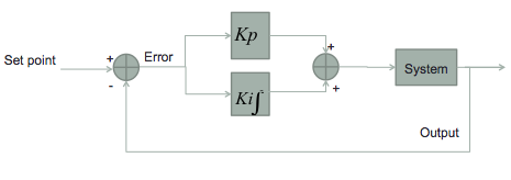
P.I Control Algorithm Block Diagram
The figure above shows a software level block diagram of the P.I control algorithm. The controller receives a current and voltage measurement which it then uses to calculate the power being drained from the battery. Once the power is measured the error signal is calculated by taking the difference between the set point and the power measured. The error signal then goes into the P.I control loop where it gets multiplied by the proportional and integral constant. The output of the P.I control is a power value and in order to convert it to a quantity that is comparable to that of the control signal, it goes through a power to PWM signal converter. The adjusted PWM signal ( output of PWM converter) then gets compared with the throttle signal, which is also a PWM signal, that is being sent by pilot,the least of the two gets sent to the controlled system. The controlled system block encompasses the battery, motor, speed controller, and limiter.
Note: It is important to state that the P.I Controller indirectly controls the power being utilized by the system by directly modifying the PWM control signal.
The P.I controller was uploaded to an Arduino Mega 2560 microcontroller. I chose the Arduino Mega2 560 microcontroller for 3 main reasons:
- Easy to program
- Broad selection of sensors (i.e current )
- Its ability to reproduce a signal to control the motor (i.e 15 pins that provide PWM output)

Arduino Mega 2560
The Arduino Mega 2560 microcontroller has an analog-to-digital converter that reads voltages and converts it to a number between 0 and 1023, so there was no need to buy an external voltage sensor. The only issue is that Arduino analog input can only be used to measure DC voltage between 0-5v. The range over which an Arduino can measure voltage can be increased by using two resistors can creating a voltage divider. For more information on voltage dividers and there design please visit the following link:
https://learn.sparkfun.com/tutorials/voltage-dividers
For measuring current I selected a 50A current sensor (AC/DC). I selected this sensor because it measured current within the range that the current gets drawn from the battery. Near max power the motor utilizes between 38-45A. In addition, as one of its biggest features it is compatible with the Arduino interface. For more specs about the current sensor please visit the link below:
http://www.dfrobot.com/index.php?route=product/product&product_id=580

DF Robot 50A Current Sensor
Check out the Results page to see how effective the P.I controller was with my propulsion system.
Recent Comments