Week three was mainly focusing on the SRG (Student Research Grant). The most important part of the SRG is the budget list. All components in the budget must be backed up with research and reasoning.
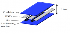
To begin, I focused on the alignment of the sensors. The goal is achieve high accuracy with the lowest amount of cost. I first did an at home experiment to find the smallest amount of area a ball would make contacting the floor. To do this, I dipped a volleyball in wet paint and placed it on a piece of paper. I did this multiple times and measured each diameter. The average diameter found was 1.5″. With an end line being 2 inches wide, there can be no dead zones. From my previous research with the FSR’s, the 2 foot long FSR was the clear choice due to cost and number of inputs needed. Because the FSR has a sensing area that is 1/4 inch wide, there needs to be three FSR’s per 2 foot sensing section in order to have no dead zones. Below is the configuration of the FSR’s on the 2″ wide boundary line.
The next parts of the budget list are the microprocessor, electronic components, and other system components.
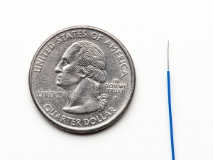
The rest of the line system, besides the sensors, consist of wires and tape. All tape is thin but the wires within the tape must also be thin. This is for safety reasons so a player does not trip over the tape. The thinnest wire I found was 0.2546 mm thick and is shown in the figure below.
With the thin wires, FSR’s and 2 layers of tape, the total thickness will only be 0.46 mm. The exploded view of the overlaying tape is shown below.
The next part to put in my SRG budget list is the electronic components. To start, I looked at the data sheet for the FSR and found that the most common circuit used was the voltage divider and buffer. A voltage divider converts the resistance change to a voltage signal. Therefore, I need one op-amp per two foot section to convert the signal as well as one resistor per two foot section. This is just a preliminary design for the circuit. Both of these parts can be provided by the Electrical Engineering program at Union.
The last part of the SRG budget list is the microprocessor. Two popular microprocessors for prototypes are the Raspberry Pi and the Arduino. Even though they come off similar from afar, they are both different from each other in certain ways. The Arduino is a microcontroller that is just a component of a computer. The Arduino is meant to control one basic program task and does not require a full computers processing power or operating system. The Arduino is also generally cheaper than the Raspberry Pi and easier to program due to most of its consumers implementing basic prototype projects. The Raspberry Pi is a full computer and therefore more powerful and complex. The Raspberry Pi is directed toward software developers and is unsuitable for simple projects.From preliminary research the Arduino seems to be the right microprocessor to use for this project.
The main specifications to look at in a microprocessor are the number of pins, memory rate, and sampling rate.
The number of pins needed depend on how many sensing areas there are. Because there are three two foot section, then there needs to be at least four input pins for this prototype (one for each section and one for the LED). But because this project will most likely expand to the whole court, the more pins the better! Though, if the product were expanded to the whole court there would be 90 wires coming out of the system, 180 foot perimeter and 90 two foot sections. Therefore in the future there would need to be a MUX as well to analyze the input pins efficiently and accurately. This is a factor to think about for the future.
The memory rate is not a high priority. The system does not need to store any inputs or outputs. The in and out line monitoring system will be processing real time data instead of recording data in small chunks. This is because for this specific system there will be no replays needed. The microprocessor will read an input signal and output either a light or no light without storing what the output was previously.
The next part of the microprocessor is the sampling rate. The sampling rate is dependent on the input signal. I will be able to further investigate this part of the microprocessor once I take the tests in Butterflied next week. For now, the Arduino MEGA 2560 is a suitable match. The MEGA has 16 input pins, which is good enough for the small prototype. It also has a large amount of memory at 256 KB and the sampling is also plenty at 16MHz.
Attached here is the submitted SRG. The budget table is found on page 3.


