11/17/14
This past week I ordered new parts in order to jumpstart the telemetry system. I determined that using the chipKit Max 32 board with the Eagle Tree air speed sensor was too difficult to continue devoting time to. Instead I have now order the Arduino Mega 2560 board and an altimeter that is known to work with the Mega. I have already found this code online and downloaded it. I verified (compiled) it on my computer using the Arduino IDE and it compiled successfully. I believe that it should be relatively easy to ‘plug and play’ once I get these parts. Then once the Mega communicates with the altimeter it should be simple to test the air speed sensor and determine if a new air speed sensor is needed or not.
Next I tried saving data to the board as if it was air speed data and I found that this process is actually straight forward. The chipKit Max 32, and the Arduino boards for that matter, have something call Electrically Erasable Programmable Read-Only Memory (EEPROM). This is a non-volatile memory and it can be written to and read from. I tested this by writing the number 12 to a couple addresses and then read this addresses. Therefore, it should be possible to store our information on the Arduino Mega in case we lose connection with the plane and we want to retrieve this data later. I found that the chipKit Max 32 board only had 512 addresses that could be written to, while the new Arduino Mega contains 4096.
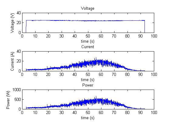
This week Ervin and I also used the new current probe and oscilloscope that John lent us from Professor Hedrick. We used this first to collect a simple 100 second reading (Appendix A). This showed us just how bouncy the current and power really are. Voltage also dips a little bit but it isn’t really all that important since it is practically a constant. However, we do see that our power can, in 0.04 seconds, jump about 100 Watts and then back down. This gives us some perspective as to just how noisy our system can be.
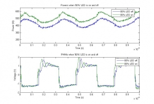
Next we soldered two connections onto the limiter. We put two wires across the ‘80%’ LED and connected these to the oscilloscope channel 3 using a coaxial cord. This allowed us to measure the voltage across the LED and what we found was rather interesting (Appendix B). Over a 100 μs range, we saw the PWM over the LED. We saved two tests, one right before the LED began to blink, and one right after the LED became solid. There is a clear difference between the PWMs and a difference of about 1 μs in width. We also found that the LED, what we have called the ‘80%’ LED, is solid when our power is peaking around 600 Watts. Next maybe we will try and measure the ‘90%’ LED and see when that LED begins to blink and then hopefully we will have a better understanding of what actually trips the limiter and for how long we can trip it before it limits us.
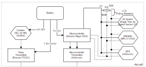
Lastly I filled in more details on the block diagram (Appendix C). My goals for this next week are to continue using the current probe with Ervin and wait for my camera and microcontroller parts to arrive. Ervin and I should be able to determine more about the limiter and how long we have above 1000 Watts before it cuts our power.
Appendix A
Appendix B
Appendix C
Recent Comments