This page shows the incident and receiving arms of the goniometer, and the optical parts we have for them. The incident end is where the X-ray tube is. The receiving end is where the detector is. In general, parts at the incident end are coded blue. Parts at the receiving end are coded red or black, or are bare metal.
Incident end
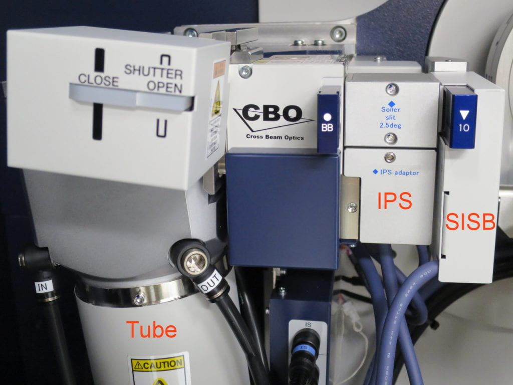
Overview of the incident end. On top of the tube is the shutter box. There’s nothing to do there but watch the lights change as the shutter opens or closes.
The CBO box (cross-beam optics) allows you to switch between a divergent “Bragg-Brentano” X-ray beam, and a parallel X-ray beam, focused using a parabolic, multi-layer mirror. The Bragg-Brentano divergent beam is selected with the BB slit (labeled BB), and the parallel beam with the PB slit. There is also a special SA slit for small angle scattering work.
IPS is the incident parallel slit adapter, typically used for a Soller slit.
SISB is the standard incident slit box. It contains the computer-controlled incident slit, which determines the X-ray illumination width (spot size parallel to the goniometer plane, left-right). This slit is set in software, and is constant for each run (it can’t be continuously narrowed at lower 2Θ angles, as far as I know). It also houses replaceable slits (10, 5, 2 mm), which determine the X-ray illumination height (spot size perpendicular to the goniometer plane). The Kβ filter can go here, in a special adapter, if for some reason it can’t go on the receiving end of the optical system.
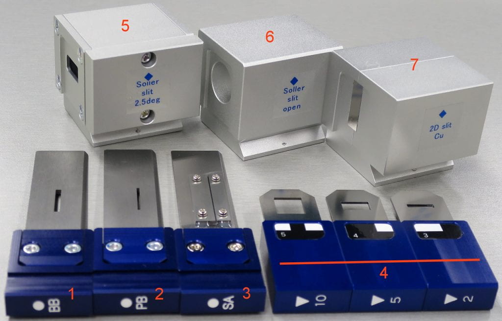
Incident end slits.
- Bragg-Brentano divergent beam slit (BB).
- Parallel beam slit (PB).
- Small-angle scattering slit (SA).
- X-ray spot size height-limiting slits, 10, 5, and 2 mm, basically for large, medium, and small area samples.
- Soller slit, 2.5°.
- Open hole, for some reason called a “Soller slit open.”
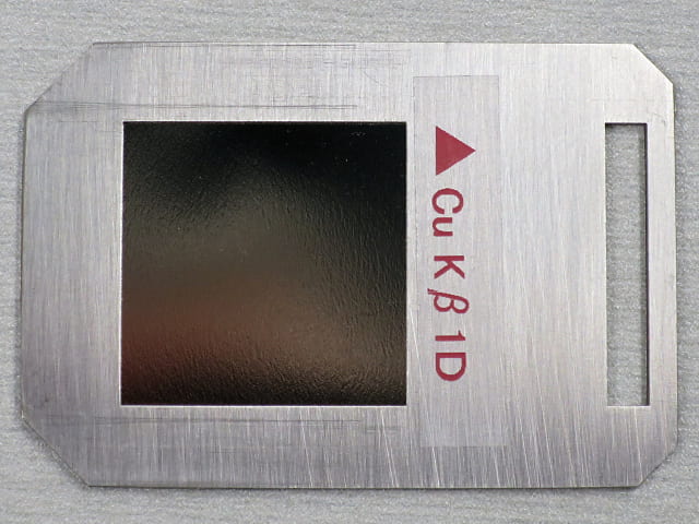
- Something called a 2d slit for copper radiation. I don’t know what it’s for. One end is covered, and the manual says it has a built-in Kβ filter, so maybe that’s what the cover is. If you use this, remove the usual Kβ filter from the beam path.
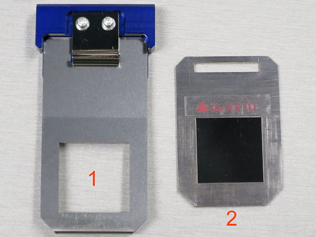
Incident Kβ filter adapter (1), with filter (2). These replace the length-limiting slit, in case you need to put the filter on the incident side rather than the receiving side
Receiving end
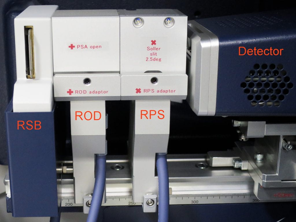
Receiving end, where the detector is. Notice that all these parts mount on a graduated rail. In general, the parts should be as far to the left as possible, and the parts touching one another. In other cases, other configurations are used. See instructions.
RSB is the receiving slit box. It has the computer-controlled receiving slit 1 (RS1), the width of which is set in software, and is constant for each run. There is also a slot for the Kβ filter, and extra absorbing plates can go in the same slot.
ROD is the receiving optical device adapter. This can hold block-type slits like the open and parallel slit analyzer.
RPS is the receiving parallel slit, mounted closer to the detector. This typically contains a Soller slit.
Detector, the Hypix 400 2-d detector array. This can be mounted horizontally (shown) or vertically, with a different base.
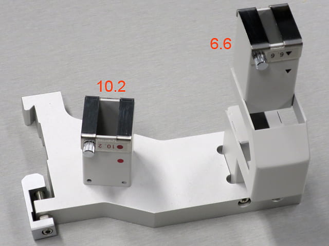
Scattered radiation protector, which reduces the amount of scattered radiation reaching the detector at small diffraction angles. That increases the peak/background ratio. The 6.6 mm section can be detached and replaced with the 10.2 mm section. This has no wire to connect to anything, and no place to put other slits or filters.
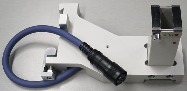
Receiving slit, 10.2 mm, reduces scattered X-rays, and is wired to hold the Kβ filter.
Nickel foil filter for removing copper Kβ radiation. It can be mounted in several different places. Fragile! Expensive! Don’t touch the foil!
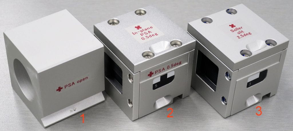
Receiving end slit blocks.
- Open block, for the ROD position.
- 0.5° parallel slit analyzer (PSA), for the ROD position. Careful, this can be installed in vertical or horizontal orientations. With blades in the horizontal position, it acts as a PSA slit, typically used in parallel-beam mode. With blades vertical it acts as a Soller slit, giving better resolution but lower signal than the 2.5° slit.
- 2.5° Soller slit for the PPS position. Careful, this can also be installed in vertical or horizontal orientations. Vertical blades are for use as a Soller slit. Horizontal blades are for use as a PSA slit for parallel beam work Don’t use two bladed (Soller, PSA) slits in tandem.

0.35 mm copper, 0.1 mm aluminum, and 0.2 mm aluminum absorber plates. They can be put in slots that also take the Kβ filter. There are several of each aluminum thickness, so they can be stacked to get the thickness you want.